
The velocimeter (timegate) is a specific electronic device that calculates the time it takes for an object to pass in front of an infrared beam a few millimeters before impact. The time in milliseconds and the object's length are then used to determine the velocity.
Why is a velocimeter so important?
The velocimeter (timegate) is a tool that will let you know if your impact has reached the desired speed. Without this tool or a simulator, it would be impossible for you to know the precise energy level of the machine at the time of impact. It is also used to determine the friction level of the testing machine.
How does it work?
The velocimeter (timegate) is the same electronic device that calculates the time it takes for an object to pass in front of an infrared beam a few millimeters before impact. The time in milliseconds and the object’s length are then used to determine the velocity.
Velocity(meter/second) = object(milimeter) / time (miliseconds)
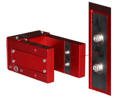
The object that cuts the infrared beam is called the flag. The flag is a small aluminum or steel plate of a preferred thickness of 0.020 to 0.100 inches. The width of the flag that we recommend is 25.4 mm. It is important to verify this value to be sure that your calculation of velocity is accurate.
Why choose the Cadex velocimeter (timegate)?
- The Cadex velocimeter (timegate) is available in different models.
- We use only the highest quality circuit boards to reduce wiring and increase precision and durability.
- From the circuit board, you can choose the output signal’s normal stat. (see figure 2 and 3)
- The system is calibrated dynamically for a constant reading.
- No UPS device needed. The system has been designed with a high-quality power supply that can take various voltages. The unit will not modify the output reading even if your electricity input is unstable.
Velocimeter (timegate) display box
The velocimeter (timegate) display box is only required for those who do not have a computer. The box receives and displays the information captured by the time gate.
More infoThe high-velocity velocimeter (timegate)
The high-velocity velocimeter (timegate) is constructed to receive larger objects than the normal velocimeter.
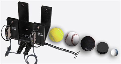
Velocimeter High Velocity
- Tennis ball
- Baseball ball
- Hockey puck
- Squash ball
- Golf ball
- etc …
Velocimeter(timegate) model for monorail machine |
Velocimeter(timegate) model for twinwire machine |
||||||||||||||||||||||||||||||||||||
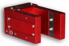 Timegate model for monorail machine |
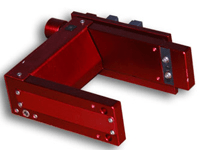 Timegate model for twinwire machine |
||||||||||||||||||||||||||||||||||||
|
|
Other caracteristics
| Cable length | Custom |
| Distance between transmitter and receiver | regular = 40 mm.
custom = up to 100 mm. available |
| Construction | Aluminum |
Internal electrical caracteristics
| Parameter | Typical values | Units |
| Internal Supply Voltage 1-2 | see figure beside | V.D.C. |
| Normally High Voltage Output 2-3 | 5 ± 0.2 | V.D.C. |
| Normally Low Voltage Output 2-3 | 0 ± 0.2 | V.D.C. |
| Transmitter voltage between A & K (high) | 1.3 ± 0.1 | V.D.C. |
| Transmitter voltage between A & K (low) | 1.3V ± 0.1 | V.D.C. |
| Receiver voltage between C & E (high) | 4.9 ± 0.1 | V.D.C. |
| Receiver voltage between C & E (low) | 4.9 ± 0.1 | V.D.C. |
| Repeatability | 0.005 | ms. |
| System precision | 0.005 | ms. |
| Digit display | XX.XX | ms. |
| Calibration precision | 0.001 | ms. |
1 The power supply voltage must be adjusted to 5.00 Volts or 5.01 Volts D.C. during the calibration adjustment sequence.
2 Any change to the power supply will modify the calibration of the unit. It should be returned for calibration to the manufacturer’s Cadex inc. technical support.
3 The voltage of the high and low states is determined by the power supply voltage. This characteristic is valid for transmitter and receiver voltage.
The following picture shows the different states of the output signal from the velocimeter system.

Figure 3
Warning!
Velocimeter
It is important – not to touch the optic sensors. The calibration could be upset.
Latched & Free Pulse
Two output signals can be selected from the back of the Time Gate box:
- Latched pulse
- Free pulse
- The latched pulse output will send only one pulsation at a time. For example, if the impactor bounces a few times during an impact test and passes more than once in front of the infrared beam, you will receive only the first signal. After an impact, the display will lock in place the last result. To unlock the latched pulse output, press the reset button in front of the Time Gate box. The display will show 00.00 ms if the gate is properly connected at the back. If the display does not reset, check the gate connections, turn the system off and then back on. If everything is OK, a green light in front of the box lets you know that you are ready for the next acquisition.
- The free pulse output will allow you to measure every event in real-time acquisition. This output is used for the calibration sequence and in measuring the coefficient of restitution. In this case, the display will show the time of the first IR cut, even if there is more on the output.
Calibration
To calibrate this system correctly, you must have a propeller with a pitch of 18° with exact dimensions. The power supply DC should be adjusted before calibration to 5.00 ± 0.01 V.D.C. then has a propeller spin between 700 and 900 RPM and no less than 650 RPM.
| Time Gate calibration schematic |
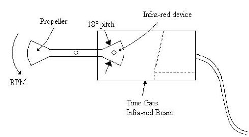 Figure 6 |
Now, with a precise scope system or using data acquisition software, you will be able to read the output signal to define de T2 value (see figure 7). Using the RPM value and the formula below, you will define the theoretical value for T1 to compare with the T1 real-time measurement. Time (in milliseconds)= ((60 minutes / speed (RPM)) / 360°) * 18° (pitch) * 1000 |
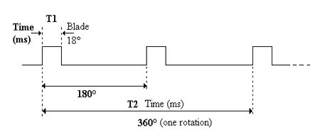 Figure 7 |
When the calculation is done, you have to use this theoretical value to compare with a real-time acquisition of the system. It will show you if the velocimeter is calibrated correctly. If the value variation is more than ± 0.02 ms, you should change the adjustable potentiometer on the internal board until you find the best match. We strongly recommend that you do not try this calibration by yourself unless you understand the whole procedure or have the knowledge/expertise required for these manipulations.
Models
In our line of electronic products, we offer two different models for the velocimeter or time gate system. These two models are for any impact drop device or velocity less than 20 meters/second.
The first model is the complete unit box with a digital display of time in milliseconds and comes with the infrared beam device that could be installed on any machine. This product is independent of any other source and has two output possibilities (latched and free pulse). ITEM # 5012
The second model is an infrared beam device assembled internally with a small electronic circuit board. The signal transportation and the powering of the unit are made with a cable of 3.6 meters long with a D-SUB 9 female connector (see pins description below). No display has been made for this model, but you need to be connected to a data acquisition system.
D-SUB 9 female connector
| Pin # | 1 | 2 | 3 | 4 | 5 | 6 | 7 | 8 | 9 |
| Description | NC | NC | NC | Led A | NC | Led K | Com | Trigger | 5 VDC |
Model #5012 can’t be used with any connection other than the one the Time Gate Box used because the IR doesn’t benefit from an internal circuit board inside the IR device. Model #5013 can’t be connected to the time gate box controller. To avoid any problems, we are using a different types of connectors. For more information about this topic, don’t hesitate to let us know your questions.